I think Andrew is most correct here. If you have no license then copyright laws are in full effect. Andrew is pointing out that there is a lot of uniformity in copyright law, although there are no doubt jurisdictions where it is not in effect.
Copyright law is in effect, license or no license. The particular question was what you can do with code that has no license. If it’s on GitHub you can probably dig out the TOS, that everyone has to agree to, where it says some things about it.
Yes, I am saying that in the US (and many other countries) one cannot legally re-use code that is copywritten. By default one may not re-publish or re-use code in the US. The point of the license is to give people rights that they would not have by default. Without the license they would be forbidden from doing many things with with code.
At least that’s how I understand this complicated question. I may be wrong, of course.
1 Like
I just looked up GitHub’s terms, which is what you sign up for if you use that.
5. License Grant to Other Users
Any User-Generated Content you post publicly, including issues, comments, and contributions to other Users’ repositories, may be viewed by others. By setting your repositories to be viewed publicly, you agree to allow others to view and “fork” your repositories (this means that others may make their own copies of Content from your repositories in repositories they control).
If you set your pages and repositories to be viewed publicly, you grant each User of GitHub a nonexclusive, worldwide license to use, display, and perform Your Content through the GitHub Service and to reproduce Your Content solely on GitHub as permitted through GitHub’s functionality (for example, through forking). You may grant further rights if you adopt a license. If you are uploading Content you did not create or own, you are responsible for ensuring that the Content you upload is licensed under terms that grant these permissions to other GitHub Users.
So you can view it and fork it, and presumably build it for yourself. It doesn’t say anything about distributing changes or distributing builds, so I’m presuming that’s a … “no”, maybe ![]()
1 Like
That would indeed be a no.
The right to fork: doesn’t give any rights to re-publish, rebrand or even reuse the code in your own work.
Note where the second paragraph says that You may grant further rights if you adopt a license (my emphasis).
These modules have been updated to today’s SDK update so that you can enjoy patching them with the new Fundamental modules.
Additionally, as per the discussion above and after receiving approval from the panel creators, this repo now has an explicit CC license. I’m looking forward to seeing the remixes!
https://github.com/mhetrick/nonlinearcircuits/actions/runs/1467578534
10 Likes
I just submitted build 2.0.1 to the user library.
Importantly, this adds a fix to Divide and Conquer where the pulse widths of the even divisors (other than /2) were incorrect. The behavior is now more accurate and predictable. However, this will have the side effect of changing how existing patches will sound if you used these outputs.
Other than that, this adds Input and Output port labels. Since 2.0.0, I added M1/ARM support to the automated build script, so that’s present here.
7 Likes
I managed to quickly get Router up-and-running. It’s now posted on the repo. I will submit it to the library soon.
10 Likes
Announcing: the Sloth collection

Michael Hetrick @trickyflemming and I are pleased to announce the release of the Sloth collection for VCV Rack. These free and open source modules are adaptations of the slow chaotic oscillators by Andrew Fitch of Nonlinear Circuits.
All are now available in the Nonlinear Circuits VCV Rack plugin.
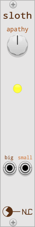
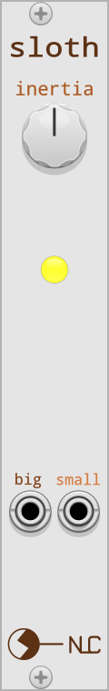
Single Sloths: Torpor, Apathy, and Inertia
Torpor, Apathy, and Inertia are 4HP modules based on the NLC Sloth Chaos. They each generate a pair of slowly changing voltages on the output ports labeled “big” and “small”. These voltages, when plotted against each other on a scope in X/Y mode, trace out a double-looping pattern reminiscent of Lorenz strange attractors. The patterns are mostly regular, but unpredictable in their timing or exact path.

In the Eurorack world, Sloth circuits are often used for generating CV and modulation signals for use in ambient or generative works.
- Torpor completes a loop every 15 seconds or so.
- Apathy takes about 60 seconds.
- Inertia can take one or two hours.
Other than the difference in speed, these three Sloths have similar behavior. The balance knob tweaks the dynamics of the chaotic orbits. It does not do anything quick or obvious; its effect is subtle and requires patience to observe. Various settings will cause the signals to spend more time traveling around one strange attractor rather than the other.
The LED indicates the polarity and amplitude of the “big” output signal. The LED is green when the “big” signal is positive or red when it is negative. When the signal is close to zero, the LED gets dimmer.
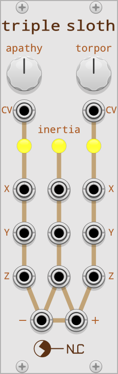
Triple Sloth

Triple Sloth is an 8HP module based on the NLC Triple Sloth. It combines Apathy, Inertia, and Torpor circuits into a single module. The Apathy and Torpor circuits add CV inputs. Inertia on the Triple Sloth has no knob or CV input. In the words of Andrew Fitch, “it does what it wants.”
The CV inputs are different in behavior from the balance knobs. They likewise require patience and experimentation, without obvious or simple rules for their effects.
Triple Sloth renames the “small” output as “X” and the “big” output as “Y”. It adds a third output called “Z” that is really just an inverted version of “Y”.
Finally, Triple Sloth feeds a linear combination of the Z signals from all three Sloths through a difference rectifier. When the combined signal is positive, the “+” output sends it and the “−” output sends 0 V. When the combined signal is negative, the “−” output sends it and the “+” output sends 0 V.
Developer technical stuff
I developed these Sloth modules for VCV Rack by analyzing Andrew Fitch’s original circuit schematics. I have documented the analysis and algorithm here. This will be interesting reading for anyone who wants to convert an analog circuit made of op-amps, resistors, and capacitors into a digital audio program.
32 Likes
Awesome, excited to have more Nonlinear circuits in VCV.
1 Like
This is an amazing addition to VCV - thank you!
1 Like
wow, thank you guys! so many new things to learn ![]()
1 Like
great to have the original available in vcv now!
triple sloth was the inspiration for my languor, which takes the idea but uses different chaotic attractors and different controls.
8 Likes
I was first introduced to Nonlinearcircuits by browsing the VCV Rack library, and I’ve been a fan ever since. I find Squid Axon particularly fascinating. But whenever I patch it, one question always comes to my mind: why did Andrew make the shift register that way? haha If you’ve never used it before, new data is sampled at every four pulses, instead of at every new pulse, like a regular shift register. Since some of you are more experienced with his designs, I thought I might ask why do you think he made it that way and how do you use this feature that makes it so unique in your patches. Cheers!
I’m not sure this really answers your question, but—as the name suggests—the module’s functionality is based on a 2003 paper about the brains of giant squids:
Only the abstract of the paper appears to be freely available: A bipolar logistic chaos neuron and its hardware implementation.
1 Like
@ecuk @bubbleandsquawk thanks for pointing me to the paper! Even though I already knew about it, I never thought of actually reading it until now haha. As a total ignorant in electrical engineering, it was as interesting of a read as it was confusing. Anyway, I’d suspect he would make adaptations to the schematics to better suit his imagination as an artist/designer.
Maybe I should ask Andrew himself? I’ve seen this question come up in another forum, so I think it’s worth trying. Let me know what you think, as well as use cases you may have found for it!
[Edit: edited out a big chunk of nonsense.]
I did, and here’s what I got:
the original design just had 2 S&H stages which only changes one at a time. If they all changed together, you would get a ‘race condition’ and have virtually the same signal on all outputs. I added 2 stages and outputs for each stage and some changes to the nonlinear feedback path. Functionally it is the same as the original, just with more outputs.
So I guess that answers it!
1 Like