Hi Folks,
I was recently asked about the Binary Sequencer and what it does so here’s a quick run down.
What it does:
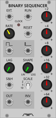
The Binary Sequencer generates repeating CV patterns based on a binary counter.
How it works:
Essentially the Binary Sequencer is just a clock divider driving a mixer. A binary counter counts up from 000000 to 111111 with each clock pulse (wrapping back around to 000000 at the end of the count). Each bit of the counter is associated with a division knob. Bit 0 = ÷2, Bit 1 = ÷4, Bit 2 = ÷8 etc. Whenever any bit in the counter is a 1, the value of the associated knob is summed to the CV output. For example, if ÷2 is set to 2 and ÷4 is set to 1 and the counter starts from 000000, the binary sequence would be 000001, 000010, 000011 etc. So, ignoring the output scaling for the moment, on the first clock the sequencer would output 2V, on the second, 1V, on the third, 3V etc. Or in other words, the value of the ÷2 knob, followed by the ÷4 knob followed by the sum of the two.
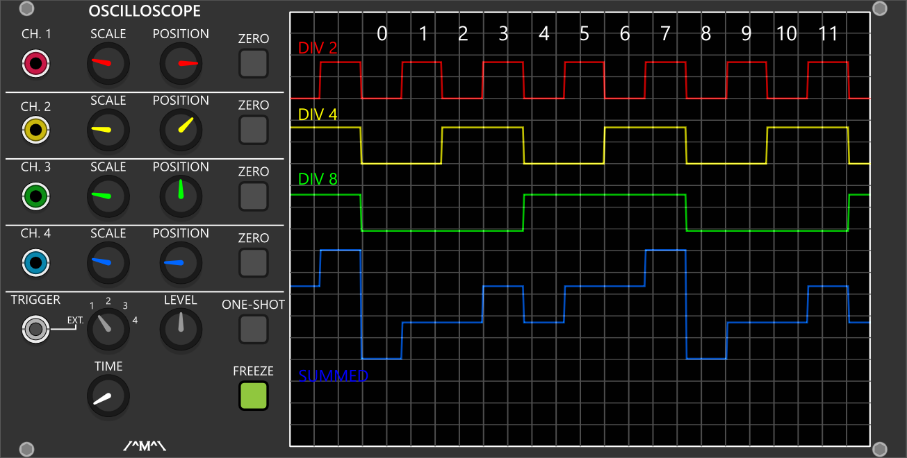
The following scope trace shows this in action. Each trace is from a separate synchronized Binary Sequencer. The red trace shows the output with the ÷2 knob set to max, the yellow trace shows the output with only the ÷4 knob set to max, green trace shows the output with only the ÷8 knob set to max, and the blue trace shows the output with all 3 set to max. As can be seen the blue trace is sum of the other three.
Output Scaling:
The knobs are configured such that they sum to the selected scale (10V, 5V or 2V) when they are all active (counter = 111111) and at their maximum positions. So for the 10 volt scale, the maximum voltage for each knob is around 1.67V.
If you set each knob to binary weighted values (0.25, 0.5, 1, 2, 4, and 8) the sequencer will generate a stepped sawtooth from 0V to the selected scale value.
The knobs are bipolar so the voltage for each bit can added to or subtracted from the summed output.
S&H Input:
When connected, the S&H input overrides the scaling section and the knobs simply become voltage dividers for the voltage that is present at the rising edge of the clock. Each knob carries the maximum value of 1/6th of the S&H voltage. For example, 6 Volts at the S&H input will mean each knob represents 1 volt when fully clockwise. This can be used to add extra variation to the binary patterns.
Run Input:
The run input accepts a gate signal not start/stop triggers. A low gate will inhibit the counter and high gate (2V threshold) will enable the counter. A flip-flop can be used to convert start/stop triggers to gates.
Expanders:
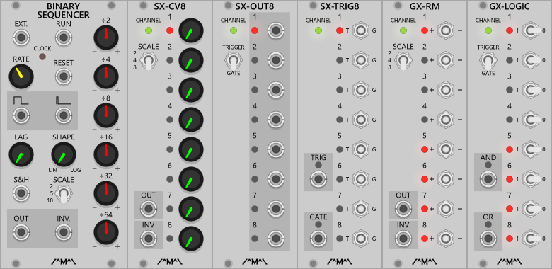
For those that aren’t aware, some of the sequencer expander modules are also compatible with the Binary Sequencer:
- SX-CV8: Sequencer CV Expander
- SX-OUT8: Sequencer Output Expander
- SX-TRIG8: Sequencer Trigger Expander
- GX-RM: Gated Comparator Expander – Random Melody
- GX-LOGIC: Gated Comparator Expander - Gate Logic
When used with the binary sequencer, the SX expanders operate on the count value so they simply step though from 1-8 in sequence. The GX expanders operate on the binary values
I hope this helps everyone understand this module a bit better.
/^M^\ Count Modula

 (checks through my collection and finds none).
 thanks for the time explaining, and Thanks for the amazing modules ! <3
